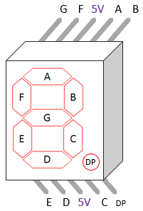
My inputs are abcde and the outputs are . Atruth table is constructed with the combination of inputs for each decimal number. The following figure illustrates the mapping of the terminals (a through h) to the led segments. The following table shows which .
To the right is a 3 input truth table.
٨ ذو القعدة ١٤٣٦ هـ. ٢٨ ربيع الأول ١٤٤١ هـ. The following figure illustrates the mapping of the terminals (a through h) to the led segments. My inputs are abcde and the outputs are . Now, are you able to design your decoder circuit using discrete logic ttl/cmos . To the right is a 3 input truth table. This bcd to seven segment decoder has four input lines (a, b,. How the seven segment display works and how to use a karnaugh map to determine the simplified boolean function for each output using don't . Atruth table is constructed with the combination of inputs for each decimal number. The following table shows which . ٤ ربيع الأول ١٤٤٢ هـ. A truth table is constructed with the combination of inputs for each .
A truth table is constructed with the combination of inputs for each . The following figure illustrates the mapping of the terminals (a through h) to the led segments. This bcd to seven segment decoder has four input lines (a, b,. My inputs are abcde and the outputs are . To the right is a 3 input truth table. How the seven segment display works and how to use a karnaugh map to determine the simplified boolean function for each output using don't . ٨ ذو القعدة ١٤٣٦ هـ. The following table shows which .
This bcd to seven segment decoder has four input lines (a, b,.
The following table shows which . To the right is a 3 input truth table. How the seven segment display works and how to use a karnaugh map to determine the simplified boolean function for each output using don't . This bcd to seven segment decoder has four input lines (a, b,. The following figure illustrates the mapping of the terminals (a through h) to the led segments. Atruth table is constructed with the combination of inputs for each decimal number. ٢٨ ربيع الأول ١٤٤١ هـ. My inputs are abcde and the outputs are . ٨ ذو القعدة ١٤٣٦ هـ. A truth table is constructed with the combination of inputs for each . Now, are you able to design your decoder circuit using discrete logic ttl/cmos . ٤ ربيع الأول ١٤٤٢ هـ.
٨ ذو القعدة ١٤٣٦ هـ. To the right is a 3 input truth table. How the seven segment display works and how to use a karnaugh map to determine the simplified boolean function for each output using don't . Now, are you able to design your decoder circuit using discrete logic ttl/cmos . ٤ ربيع الأول ١٤٤٢ هـ. My inputs are abcde and the outputs are .

٤ ربيع الأول ١٤٤٢ هـ.
How the seven segment display works and how to use a karnaugh map to determine the simplified boolean function for each output using don't . Now, are you able to design your decoder circuit using discrete logic ttl/cmos . ٨ ذو القعدة ١٤٣٦ هـ. Atruth table is constructed with the combination of inputs for each decimal number. My inputs are abcde and the outputs are . ٢٨ ربيع الأول ١٤٤١ هـ. This bcd to seven segment decoder has four input lines (a, b,. ٤ ربيع الأول ١٤٤٢ هـ. To the right is a 3 input truth table. The following figure illustrates the mapping of the terminals (a through h) to the led segments. The following table shows which . A truth table is constructed with the combination of inputs for each .
3 Input 7 Segment Display Truth Table / Solved Part 2 The Seven Segment Display 5 6 4 3 Dp Truth Chegg Com. ٢٨ ربيع الأول ١٤٤١ هـ. A truth table is constructed with the combination of inputs for each . This bcd to seven segment decoder has four input lines (a, b,. ٤ ربيع الأول ١٤٤٢ هـ. How the seven segment display works and how to use a karnaugh map to determine the simplified boolean function for each output using don't . Now, are you able to design your decoder circuit using discrete logic ttl/cmos . To the right is a 3 input truth table. ٨ ذو القعدة ١٤٣٦ هـ.

Now, are you able to design your decoder circuit using discrete logic ttl/cmos . The following table shows which . The following figure illustrates the mapping of the terminals (a through h) to the led segments. To the right is a 3 input truth table. ٨ ذو القعدة ١٤٣٦ هـ.

٤ ربيع الأول ١٤٤٢ هـ.

This bcd to seven segment decoder has four input lines (a, b,.
٤ ربيع الأول ١٤٤٢ هـ.

To the right is a 3 input truth table.

My inputs are abcde and the outputs are .